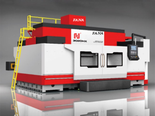
1. Fault phenomenon: In the high-speed gantry machining center, the CNC system is FANLiC OM – whether in MDI or AUTO mode, the machining center sends a spindle speed command. When the start button is pressed, the machine tool PLC immediately sends an alarm message of “spindle unit failure”. Observe that the alarm number of the spindle servo unit in the electrical cabinet is AL-12.
Fault diagnosis: Alarm number AL-12 indicates that there is an overcurrent on the DC side of the inverter circuit of the spindle unit. Disassemble the front control board and middle power control board of the machine tool spindle unit to expose the two 150A high-power IGBT transistor modules at the bottom. Each ICBT module is encapsulated with 6 IGBT transistors and 6 damping diodes, forming two sets of three-phase fully controlled bridges for rectification and inversion, respectively. Using a multimeter to measure according to its pin diagram, it was quickly discovered that there was a short circuit in the ICBT tube in one of the transistor modules.
2. The fault has been identified, and it seems that as long as a transistor module is purchased and replaced, the spindle unit can be repaired. But it cannot be dealt with simply like this, the important issue is to identify the root cause of the fault. After inquiring about the fault process with operator I, the operator said that when the spindle box moves to different positions, the spindle can sometimes work normally, and sometimes it cannot. Especially when the spindle box moves along the crossbeam (i.e. the r-axis) of the machine tool, the spindle can operate normally at certain positions. To determine the connection between the occurrence of the fault and the position of the main axle box, climb onto the crossbeam and carefully observe the movement of the main axle box, quickly identifying the cause of the fault. The original spindle box, as the r-axis of the machine tool, moves along the crossbeam. The power line and feedback line of the spindle motor are connected to the electrical cabinet through a cable drag chain, which moves along with the spindle box on the crossbeam. Although the material of the drag chain is engineering plastic, the connecting pins between each section are metal. When the cables in the drag chain move together with the drag chain, the insulation skin of the cables rubs against the connecting pins. Over time, the insulation skin is worn out, revealing the metal wire in the middle. When the spindle moves to a certain position, the metal wire in the cable collides with the metal connecting pin, and the connecting pin fork directly collides with the bed of the machine tool, Causing a short circuit to ground in the power line of the spindle motor, the power transistor module of the machine tool spindle drive unit was broken down. This is the root cause of the damage to the ICBT module.
3. Troubleshooting: Replace the transistor module, handle and replace worn cables, and improve the fixing method of the cables in the drag chain to prevent friction between the cables and the connecting pins. After this repair, no similar faults have occurred again.

